Why is it called a concentric butterfly valve?
What is a Concentric Butterfly Valve?
A concentric butterfly valve is crucial for fluid control systems. It features a metal disc positioned at the center of a pipe, which rotates to manage fluid flow. This rotation provides efficient control with minimal resistance.
Design Characteristics of Concentric Butterfly Valves
Concentric Disc Placement: Notably, the disc is centered within the valve body. Thus, when the valve is fully open, it aligns with the pipe’s centerline. This design significantly reduces flow obstruction.
Circular Disc Shape: Furthermore, the disc’s circular shape resembles butterfly wings. Consequently, this shape enables smooth flow regulation and reduces pressure drop.
Rotational Movement: The disc rotates around its central axis, controlling fluid flow effectively. This simple quarter-turn operation makes the valve easy to adjust quickly.
Sealing Mechanism: Moreover, a resilient seat or lining creates a tight seal between the disc and the valve body. Therefore, it prevents leakage when the valve is closed.
Materials and Construction: Manufacturers typically use stainless steel, cast iron, or PVC for these valves. The choice of material depends on the specific application and fluid compatibility.
Actuation Options: Users can manually operate these valves with a hand lever or wheel. Alternatively, pneumatic, electric, or hydraulic actuators can automate the valves. This automation allows for remote control and monitoring.
Versatility: Due to their simple design and reliable performance, concentric butterfly valves are highly versatile. They are suitable for applications in water treatment, HVAC systems, chemical processing, and oil and gas pipelines.
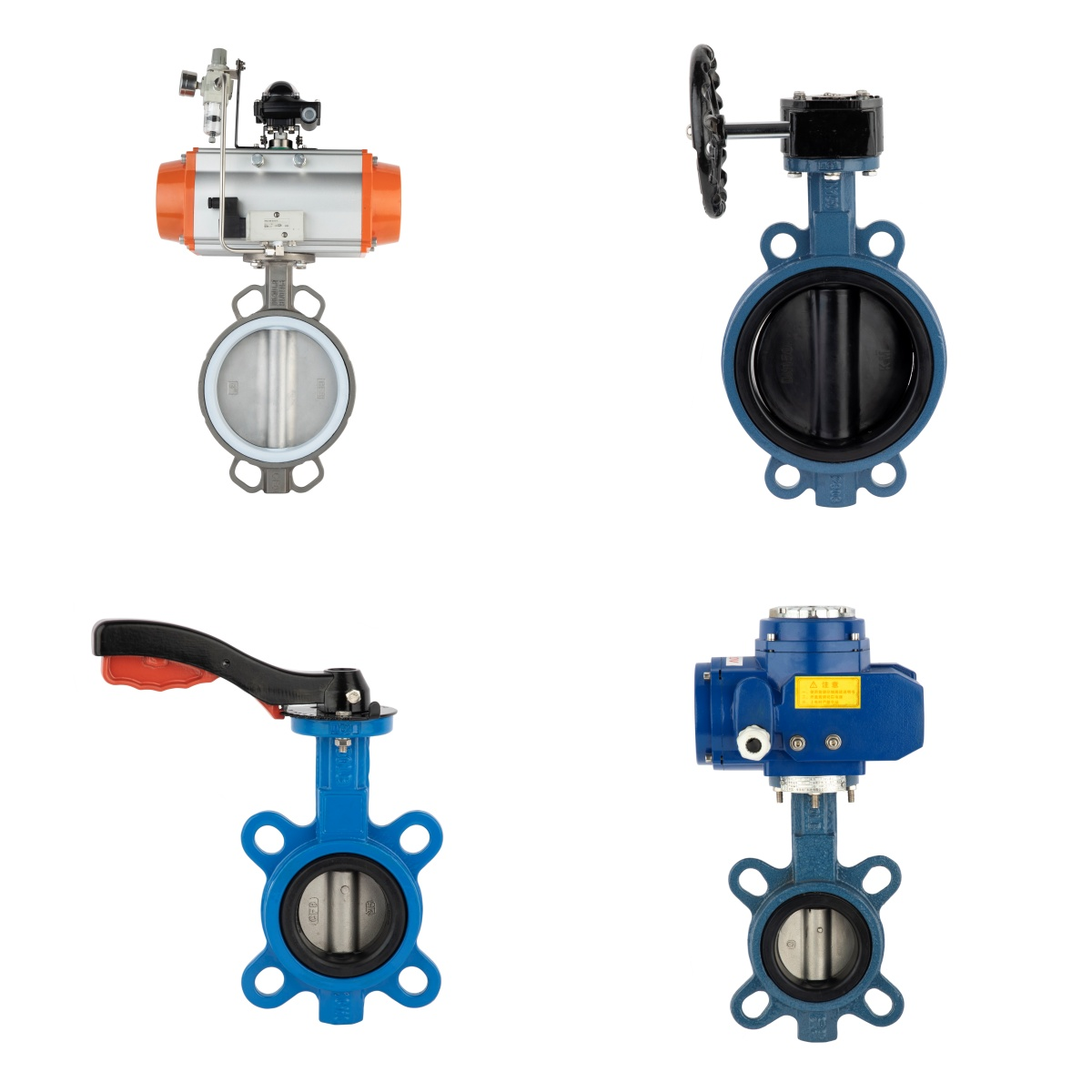
Types of Driving Methods for Concentric Butterfly Valves
Manual Operation: This method involves using a hand-operated lever or handwheel. It turns the valve stem and controls the disc position.
Gear Operator: For larger valves requiring more force, a gear operator is used. It includes a gearbox attached to the valve stem, making manual operation easier.
Pneumatic Actuation: Pneumatic actuators use compressed air to drive a piston or diaphragm, which rotates the valve stem. This method offers fast operation and precise control.
Electric Actuation: Electric actuators use an electric motor to rotate the valve stem. They integrate well into automated systems, providing continuous and precise control.
Hydraulic Actuation: Hydraulic actuators employ hydraulic fluid to drive a piston or cylinder, rotating the valve stem. This method is ideal for high-pressure or high-torque applications due to its significant torque output.
Solenoid Actuation: Solenoid actuators use an electromagnetic coil to actuate a plunger, rotating the valve stem. They are suitable for on-off control and can be integrated into automated systems for remote operation.
In summary, each driving method has distinct advantages. Consequently, the choice depends on specific application requirements, operating conditions, and available resource